| Basic Fingernail Gouge Grinding Jig | ||
|
Note: This Jig will aid the forming of a fingernail profile on a Spindle Gouge and a Bowl Gouge, it does however provide only limited ability to alter the bevel angle because of its fixed nature. |
||
|
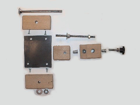
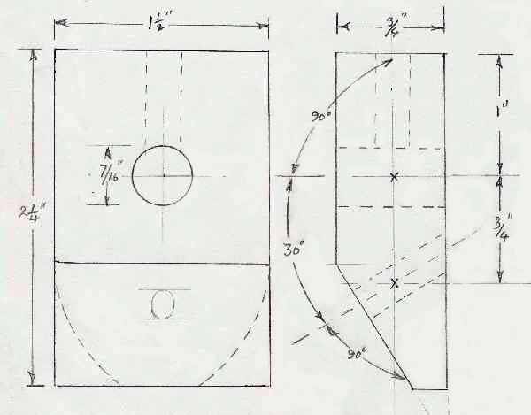
Objective: 1. To make a Fingernail Gouge grinding Jig Reasons: 1. A need to produce an acceptable grinding result on the basis that I kept making a hash of freehand grinding this form. 2. The cost of commercial units will be better spent on improved quality Grinding wheels. Design criteria: 1. To provide the equivalent function of the commercial units. 2. To do it with components/materials readily available in a wood shop. Materials used: 1. 4 pieces of Beech of 19 X 38 mm section. 2. 2 X 6 mm threaded inserts. 3. 90 X 80 X 3 mm metal plate. 4. 4 small wood screws 5. 6 mm. Studding, nuts (3) Nylock nut, washer 6. 6 mm clamping Knob from unused grinder rest bracket. 7. 8mm Coach Bolt nut & washer. |
||
 |
 |
|
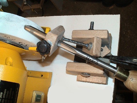
| Jig in use during initial trials | ||
 |
 |
|
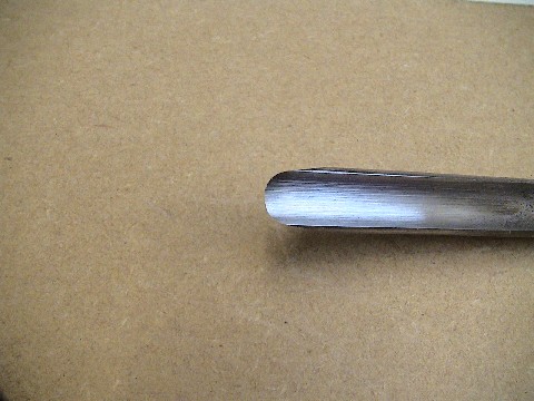
| First profile produced in initial trial | ||
 |
 |
|
| Component Parts | ||
|
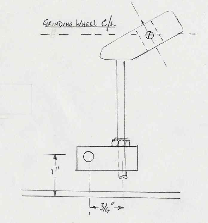
Some points on construction to note:
The two sketches below give a guide to dimensions and set up, the dimensions are not super critical as the final angle of grind is dependant on user set up, the distance between the Pivot Rod hole centre and the Gouge hole centre govern the curvature of the ‘fingernail’. The 120 deg. Angle of the Pivot Rod puts the Gouge wheel approach angle in the correct “ball park” so to speak. |
||
 |
 |
|
|
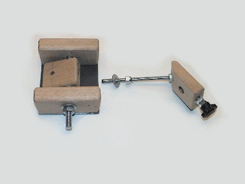
My one and only finger gouge was 7/16” diameter when I made this and I
made the hole to fit, a larger diameter hole with a Centralizing Vee at the
lower edge would accommodate a bigger range of sizes. The 6mm studding is locked to the Gouge Clamp Block with a nut. The Studding (Pivot Rod) is free to swing in the lower block. Guidance notes will give a pilot hole size for the Thread Inserts somewhat smaller than you will need for use in Beech (I taper drilled mine in steps from 7.5 -9mm) I have found it prudent to fit a locking nut to the Gouge clamp screw assembly which is tweaked up after thumb tightening gouge in situ. I rounded the clamp screw inner end to match the Gouge inner face To set up: Determine the height of the mounting relative to the grinder and check that the Centreline of the Gouge locating hole is at or above the Grinding Wheel Centre Line when positioned as per sketch. Fit Gouge to jig with approx 2” (50mm) protruding on Wheel side. WITH GRINDER STATIONARY. Position and secure base adjacent to grinder and offer Gouge up to wheel. Adjust the temp 2” extension (in or out) until the Gouge face to be ground is sitting on the wheel at the correct angle. Swing the pivot from side to side to check that the gouge remains in contact with the wheel (if jig or lower pivot block is to far to one side gouge may not stay in contact) Check that the jig does not foul grinder casing or guards. Withdraw Gouge on pivot and switch on grinder. Start with Gouge fully to one side and offer up to wheel, with hand on Gouge handle and a finger resting on top of Gouge near the handle side of jig clamp and with Light Pressure only, rock the jig from one side to the other until you have a continuous facet across the back face of the Gouge. Observations Only improvement that is immediately obvious is to the Pivot Rod, think it would benefit from the fitting of Pivot Rod with a Plain lower portion. (Never did get round to doing this and Jig is still useable some 4 yrs later) |
||
| This Jig first appeared in UKWorkshop thread in May 2005 | For a Jig giving more flexibility of Bevel Angle see this version. | |